HRM-V™ System Description
Heat Pipe Technology split passive (HRM-V™) energy recovery heat pipes are an air to air heat exchange system designed to move heat from one air stream to another. Split passive HRM-V™ heat pipes provide economical and reliable recovery for summer only, winter only, or summer and winter applications, where supply and exhaust air streams are remotely located. These systems are designed for both process and comfort applications to pre-cool or pre-heat outside air using otherwise wasted heat from exhaust air. A combination of pressure differentials, circuit design, and thermosiphon effect, help circulate the working fluid from the supply air section to the exhaust air section where it changes phase from a liquid to a vapor and back to a liquid. Because of this natural phase change unique to heat pipes, the HRM-V™ system can produce higher heat transfer capabilities than a comparable water glycol system. Best of all, because they have no moving parts HPT heat pipes require minimal maintenance and provide passive, reliable energy recovery with Zero Cross Contamination.
Construction
Coil construction consists of tube and fin design with copper tubes and aluminum or copper fins. The coils are encased on top, bottom and sides with either galvanized or stainless steel casing for easy installation into air handling units or duct work. Top and bottom headers are type L copper. Header size will vary based on the capacity of the coil. Each coil is made up of two rows that make up one circuit, to be piped in a counter flow arrangement, and individually charged for maximum heat transfer effectiveness. The tubes of the coil are configured vertically with fins oriented horizontally. The HRM-V™ system can be configured with 2, 4, or 6 rows. However, a typical HRM-V™ heat pipe system will use 6-rows. Air pressure drop and fan power increase with each row. Coil depth is based on the number of rows.
Typical dimensions shown in fig 1 & 2. Overall dimensions are vary with header size.
- Tubes – 1/2 inch OD copper
- Fins – aluminum or copper, sine wave pattern
- Casing – G90 galvanized, or 304 stainless steel
- Headers – Type L, ACR copper, pipe sizes based on capacity
- Coil Sizing
- Face Height – maximum face height is 75” inches per coil for systems with fixed offset, 60” for the two season DSO™.
- Face Length – maximum face length is 155 inches per coil
- Coatings – E Coat, Phenolic, or other commercially available coatings are provided when specified.
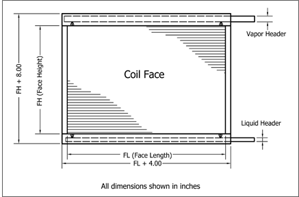
Figure 1 - Typical height and length dimensions
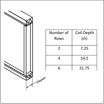
Figure 2 - Typical depth dimensions
Installation Configurations
When installed on the same elevation, the HRM-V™ system can transfer heat in both directions, delivering summer and winter recovery. For installations where one air stream is elevated, the HRM-V™ system will work well in one recovery mode (heat or cool), with some to no recovery in the other season, depending on the vertical separation difference between supply and exhaust. Fixed offset systems tend to be the more economical and higher performing from total BTUs stand point, especially in predominantly heating recovery climates. However this is dependent on climate and specific conditions entering the system. An energy analysis should help determine which of the below arrangements will yield the best results and the lowest cost.
A. Optimized For Heat Recovery
When cooler outside air is above warmer exhaust air
-Maximum 120 ft. separation
This system is suited to mainly heat (winter) recovery climates, but usually yields the most BTUs annually even in most southern US climates. This is due to the higher temperature differential in winter recovery mode. Depending on the vertical offset between supply and exhaust, appreciable summer recovery can take place as well.

Figure 3 - Winter heat recovery
B. Optimized For Cool Recovery
When warmer outside air is below cooler exhaust air
-Maximum 120 ft. separation
This system is suited to mainly cold (summer) recovery climates where summers are long with high temperatures. Again, depending on vertical offset between supply and exhaust section, appreciable recovery can take place in winter as well.
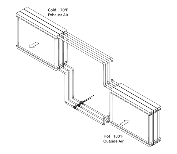
Figure 4 - Summer cool recovery
C. Dynamic Seasonal Offset (DSO™) For Equal Heat/Cool Recovery
When outside air is on the same elevation as exhaust air
-Maximum 120 ft. separation
This unique design allows for a side by side system where Supply and exhaust are on the same level to attain equal cool and heat recovery through a Dynamic Seasonal Offset, utilizing integral partial face dampers and actuators that optimize performance by directing air flow through sections of the heat pipes to create an offset effect. Actuators and dampers are set up to take 115 VAC signal for one mode of operation and, when power is removed, the dampers switch to their opposite state (open to close and close to open) for the other season.
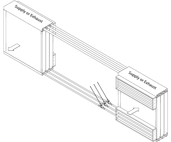
Figure 5 - Equal heat/cool recovery
Comfort Energy Recovery
HPT split passive energy recovery heat pipes can be used for comfort-to-comfort or for process applications. Comfort-to-comfort applications include heating only recovery, cooling only, or more often, both heating and cooling recovery. Split passive energy recovery heat pipe systems are used for heating/cooling recovery from cold northern zones with harsh winters to the heat of more southern climates.
Process Energy Recovery
For process applications, heating/cooling recovery can also take place in either direction. Process applications frequently involve air temperatures elevated above normal room conditions. The heat pipes can be made to withstand temperatures up to 150°F. For air streams with corrosive components, the heat pipes can be provided with a protective coating. Heat pipes can also be fabricated with both fins and tubes made of copper.
Design Considerations
The HRM-V™ system allows for multiple coil sections to be utilized for applications with larger airflows. The HRM-V™ system design permits one supply section to be used for each exhaust coil section Furthermore, supply and exhaust coils can be sized differently to handle unequal supply and exhaust airflows. Figures. For maximum heat transfer, air streams must be piped in counter flow. Counter flow operation is where two air streams are arranged such that they flow in opposite directions through the heat pipe coils. If necessary, due to design considerations, the air streams may need to flow in the same direction through the heat pipe, then counter flow can still be achieved through connecting the liquid and vapor headers in a counter flow fashion. See Figure 6. Other piping arrangements are show as well.
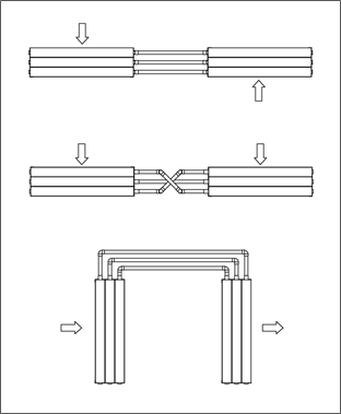
Figure 6 - Counter flow piping
Operation
For an HRM-V™ system where supply and exhaust coils are located on the same level with a Dynamic Seasonal Offset ™, the integral partial face dampers and actuators will optimize performance by directing air flow through sections of the heat pipes to create an offset effect. Dampers and actuators are operated in the on/off position and installed on the dampers so, when there is no power, the system defaults to the heating optimized mode. Heat transfer is driven by air temperature differentials which cause the working fluid to change phase liquid to vapor in the warm side and from vapor to liquid in the cold side. This phase change absorbs and releases tremendous amount of energy to the air streams in both directions. The higher the temperature differential between supply and exhaust the better the system performs. Operation of heat pipes is automatic by refrigerant circulation and needs no further attention. The coils are fully pressure tested and will give many years of trouble-free operation.